Availability:
Delivered within 3-5 working days
Only small number of pieces available
Availability near you
Check store availability
Information & Downloads
Our service

Order hotline
+49 (0)9181 / 330 100Mon. - Sat.: 8:00 - 20:00 hrs
Specialist advice
ARRANGE CALLBACKMon. - Fri.: 9:00 - 16:00 o'clock
Secure payment with SSL encryption
Free return
Up to 5% bonus with the Berger advantage card
Product details
| Protects 12, 24 and 48 V systems | Protects each individual cell of a lithium battery |
Product description
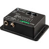
Protects each individual cell of a lithium iron phosphate (LiFePO4 or LFP) battery
Each individual cell of a LiFePO4 battery must be protected against overvoltage, undervoltage and overtemperature. Victron LiFePO₄ batteries have a built-in cell balancing, temperature and voltage control (in English: Balancing, Temperature and Voltage control hence the acronym: BTV). They are connected to the VE.Bus BMS via two sets of M8 circular connectors. The BTVs of several batteries can be linked together. Up to five batteries can be connected in parallel and up to four batteries in series (BTVs are simply daisy-chained), so that a 48 V battery bank with up to 1500 Ah can be assembled. For more details, please refer to the technical documentation of our LiFePO4 battery
Tasks of the BMS
Protects 12V, 24V and 48V systems
Operating voltage range of the BMS: 9 to 70V DC
Communicates with all VE.Bus products
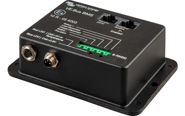
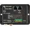
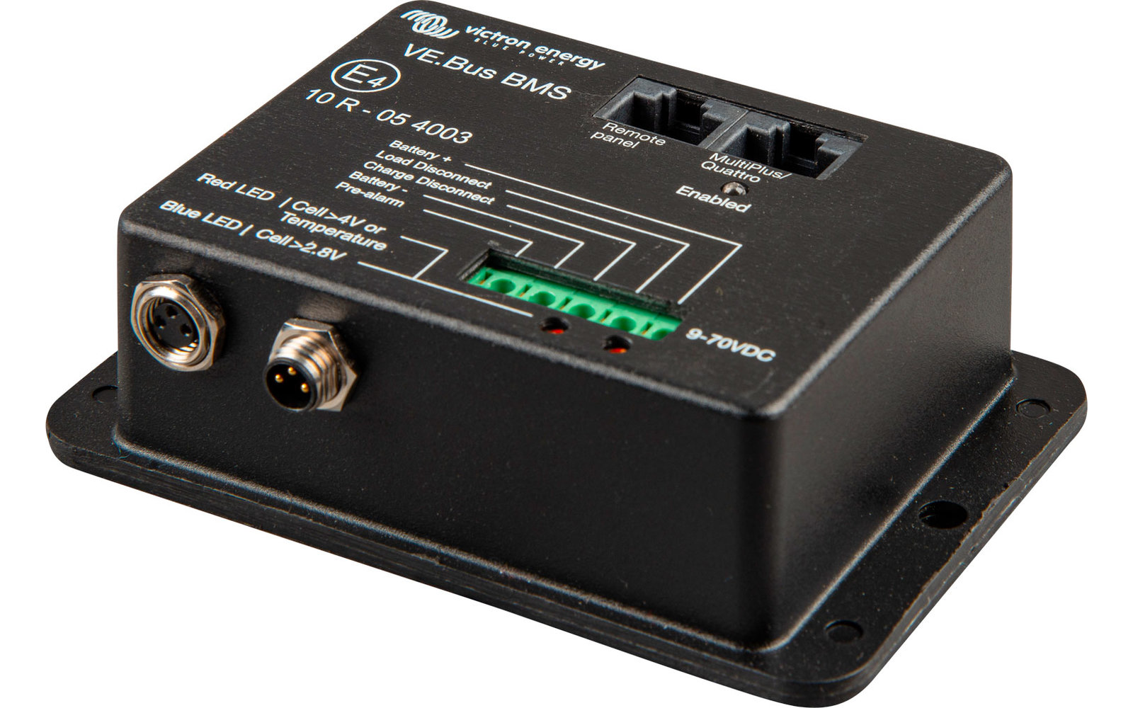
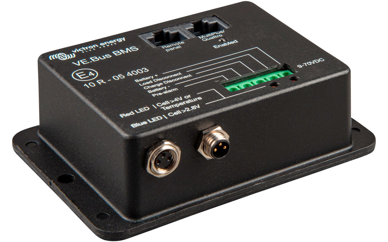
The VE.Bus BMS can be connected to a MultiPlus, Quattro or Phoenix inverter device. The connection is made via a standard RJ45 UTP cable
Other products without VE.Bus can be controlled as follows
Load disconne ction
Load separation is normally high and becomes free floating when a cell is live (standard 3.1 V/cell, adjustable at the battery between 2.85 V and 3.15 V per cell). Maximum current: 2 A. The load disconnect output can be used to control - the remote on/off switching of a load and/ or - the remote on/off switching of an electronic load switch (battery protection)
Pre-alarm
The pre-alarm output is normally free floating and goes high when cell undervoltage is imminent (standard 3.1 V/cell, adjustable at the battery between 2.85 V and 3.15 V per cell). Maximum current: 1 A (not short-circuit proof). Minimum delay between pre-alarm and load disconnection is 30 seconds
"Charge Disconnect
The Charge Disconnect output is normally HIGH and will "free float" when a cell overvoltage or overtemperature is imminent. The Charge Disconnect output can be used to control the following functions:
LED displays
Each individual cell of a LiFePO4 battery must be protected against overvoltage, undervoltage and overtemperature. Victron LiFePO₄ batteries have a built-in cell balancing, temperature and voltage control (in English: Balancing, Temperature and Voltage control hence the acronym: BTV). They are connected to the VE.Bus BMS via two sets of M8 circular connectors. The BTVs of several batteries can be linked together. Up to five batteries can be connected in parallel and up to four batteries in series (BTVs are simply daisy-chained), so that a 48 V battery bank with up to 1500 Ah can be assembled. For more details, please refer to the technical documentation of our LiFePO4 battery
Tasks of the BMS
- Shuts down or disconnects loads in the event of imminent undervoltage
- Reduce charge current in case of imminent cell overvoltage or overtemperature (only for VE.Bus products, see below)
- Switching off or disconnecting the battery chargers in the event of an imminent cell overvoltage or excess temperature
Protects 12V, 24V and 48V systems
Operating voltage range of the BMS: 9 to 70V DC
Communicates with all VE.Bus products
The VE.Bus BMS can be connected to a MultiPlus, Quattro or Phoenix inverter device. The connection is made via a standard RJ45 UTP cable
Other products without VE.Bus can be controlled as follows
Load disconne ction
Load separation is normally high and becomes free floating when a cell is live (standard 3.1 V/cell, adjustable at the battery between 2.85 V and 3.15 V per cell). Maximum current: 2 A. The load disconnect output can be used to control - the remote on/off switching of a load and/ or - the remote on/off switching of an electronic load switch (battery protection)
Pre-alarm
The pre-alarm output is normally free floating and goes high when cell undervoltage is imminent (standard 3.1 V/cell, adjustable at the battery between 2.85 V and 3.15 V per cell). Maximum current: 1 A (not short-circuit proof). Minimum delay between pre-alarm and load disconnection is 30 seconds
"Charge Disconnect
The Charge Disconnect output is normally HIGH and will "free float" when a cell overvoltage or overtemperature is imminent. The Charge Disconnect output can be used to control the following functions:
- remote switching on/off of a charger and/or
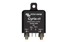
- a Cyrix-Li charger relay and/or
- a Cyrix-Li-ct battery coupler.
- Maximum current: 10 mA
LED displays
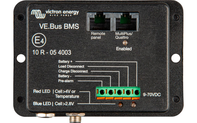
- Switched on (blue): the VE.Bus products are switched on.
- Cell >4V or temperature (red): the Charge Disconnect output is LOW because a cell overvoltage or overtemperature is imminent.
- Cell >2.8V (blue): "Load Disconnect" output is HIGH.
Technical data:
- Input voltage range: 9 - 70 V DC
- Current consumption normal operation: 10 mA (current for "Load Disconnect" not included)
- Low cell voltage current consumption: 2 mA
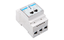
- VE.Bus interface: Two RJ45 sockets for connection to all VE.Bus products
- Operating temperature: -20 to +50°C
- Humidity: max. 95 % (non-condensing)
Features
| Type battery | Accessories |
| Colour | black |
| Depth | 32 mm |
| ean | 8719076021032 |
| Manufacturer Article No. | BMS300200000 |
Legal information
Manufacturer information
Accusysteme TransWatt GmbH
Am Tiggemann 4
59505 Bad Sassendorf
Germany
matyschik@transwatt.de
Our service

Order hotline
+49 (0)9181 / 330 100Mon. - Sat.: 8:00 - 20:00 hrs
Specialist advice
ARRANGE CALLBACKMon. - Fri.: 9:00 - 16:00 o'clock
Secure payment with SSL encryption
Free return
Up to 5% bonus with the Berger advantage card
- Similar items
- More from this brand


